
Pertronix Install
by Jeff Finley
A common and easy to install aftermarket upgrade to our cars is the Pertronix IgnitorTM. The Pertronix IgnitorTM replaces the points and condenser inside the distributor. There are enough questions on the messageboard that warrants a little how-to article. Disclaimer warning: in no way shape or form are we affiliated with, evaluating, endorsing, recommending or not recommending this product.
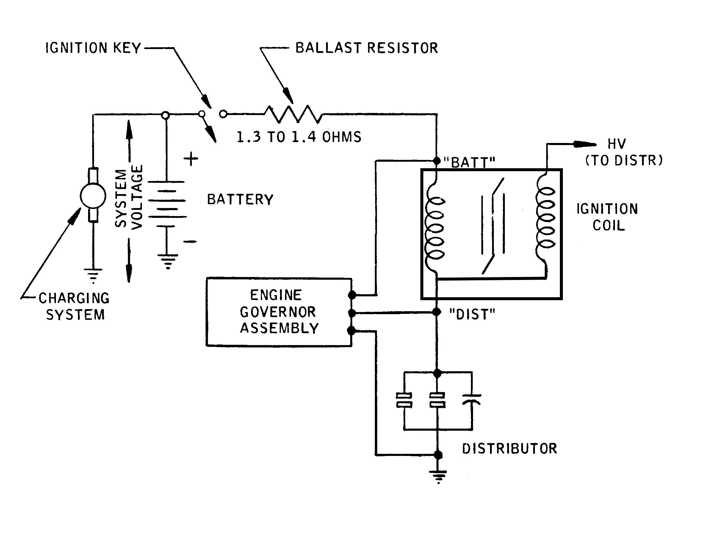
The drawing (schematic) below shows the generic ignition circuitry including the Rev Limiter (Engine Governor Assembly) (more about the Rev Limiter here) but without a tachometer as originally installed by Ford. The ballast resistor is actually resistance wire (sometimes referred to as the fat pink wire) in your vehicle which has more resistance than regular wire (nearly zero resistance).
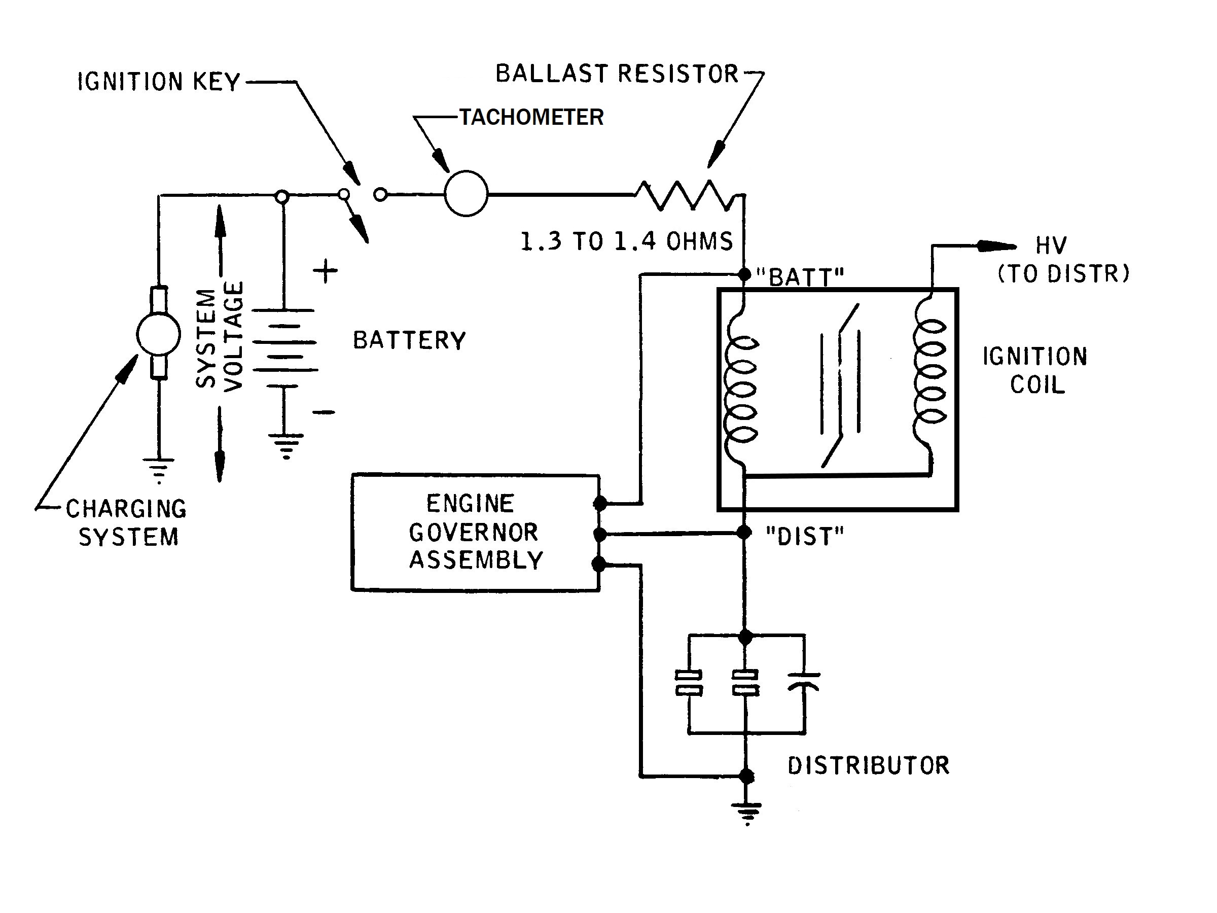
The next schematic shows the ignition circuitry with the original Ford tachometer. The tachometer is in series in the ignition circuit. This is why a bad tachometer can make your vehicle run poorly or not at all because it will interrupt the ignition circuit. The first thing people will often say when a vehicle is not running is to disconnect the tachometer and jumper the wire harness tachometer connector. A tachometer is not required for the vehicle to run and has no direct impact on the Pertronix IgnitorTM wiring.
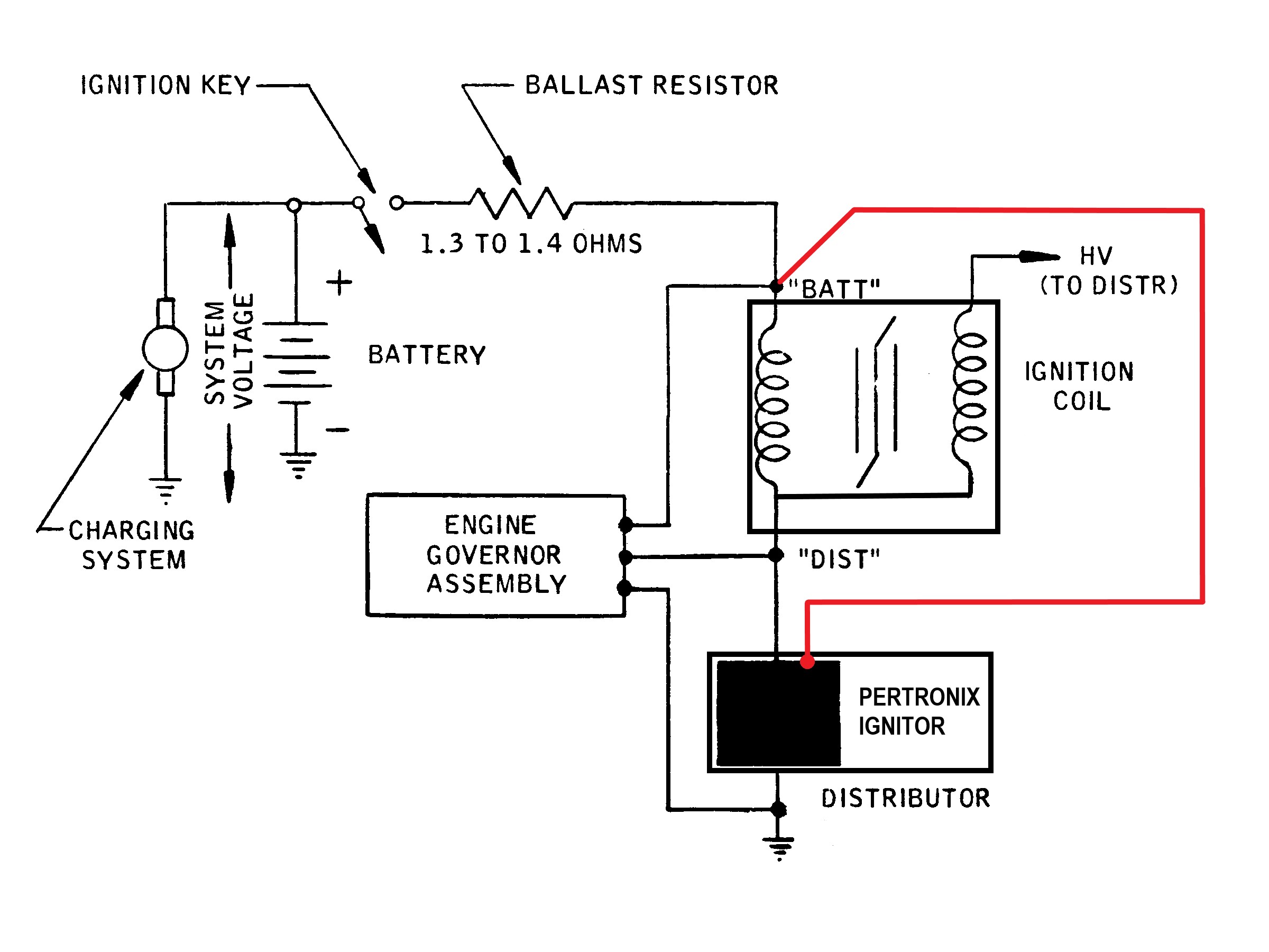
Pertronix specifies their system requires 8 volts (V) minimum and 16V maximum. The minimum voltage is our biggest concern here. First thing to do, with car running, is measure the voltage between the "BATT" terminal on the coil and the negative terminal on the battery. Is the voltage consistently stable above 8.0V? If yes, you can power the system using the coil terminal as shown below.
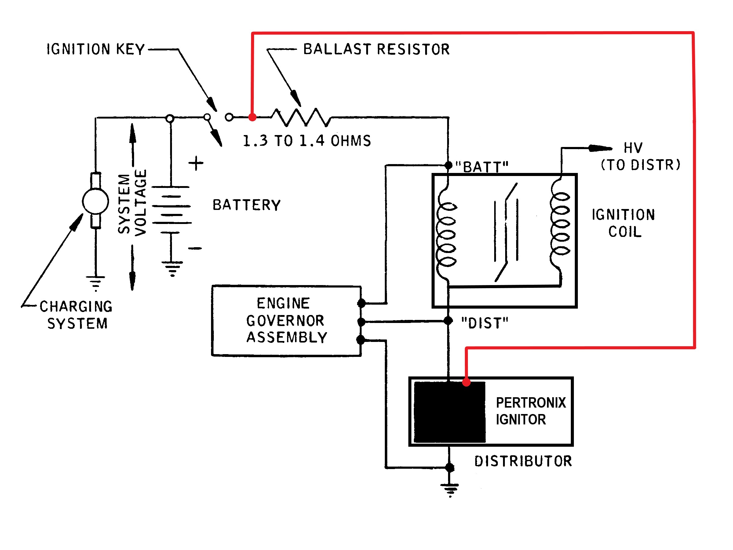
If your voltage measurement between the "BATT" terminal on the coil and the negative terminal on the battery is below 8.0V, inconsistent or just barely above 8.0V you need to run another wire from a Start/Run +12V circuit to the Pertronix IgnitorTM for it to operate reliably. See schematic below. Note there is no tachometer in this schematic. Make this connection (in red) ahead of and away from the tachometer if you have one.
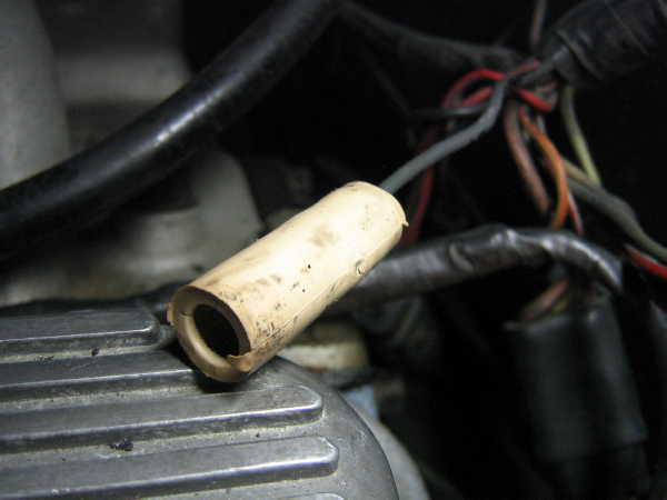
The easiest way to do this in the BOSS 302 is to use the carburetor solenoid wire. It is a Start/Run +12V source already under the hood. This is the blue wire with the white female terminal that exits at the center-left dash panel shown below.
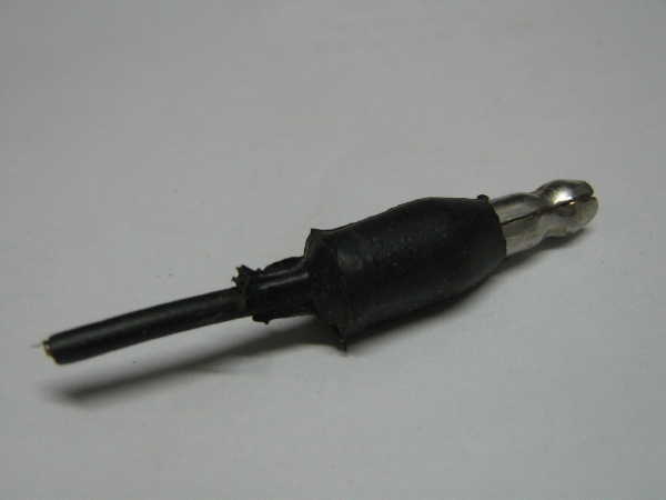
You will also need a male (bullet) terminal (similar to the one shown below) to splice or solder to the Pertronix IgnitorTM red wire and connect to the existing solenoid wire terminal.
If you have the carburetor solenoid installed you will not need a male terminal but you will have to connect (solder) the Pertronix red wire to the existing solenoid feed wire (or find an alternative Start/Run +12V source and run the Pertronix red wire there but that is beyond the scope of this article).
If you are currently running a 12V coil then you should have already bypassed or eliminated the Ford harness ballast resistor (resistance wire) with your own Start/Run +12V wire and can probably attach the Pertronix power wire to it at the coil.

Please note: use this information at your own risk. While we believe this information to be correct, we are not responsible for damage to your car or parts. Always refer to the manufacturer's installation instructions.
This page last updated: April 1, 2023. All Rights Reserved.