
Mustang Tach Cluster Conversion
by Erich Bozzer
How many times have you seen a Tach Instrument Cluster at a swap meet and thought that it would be nice to replace your base instrument cluster? You look further and find out that in order to perform this change you also need the unique wire harness that goes with it. Then you learn that the wire harness is either missing or too expensive. Anyway do you really want to tear your whole dash out to replace the wiring? Good news, now you can modify your existing base wiring to be used with the Tach Cluster.
As you know, when the Tach was put into the right center pod of the cluster it forced the temperature and fuel gauges to move to the two outer pods. Ford replaced the charge and oil pressure gauges with warning lights. All these changes can be summed up into 4 categories: 1) Pin-out changes in the connector on the back of the cluster. 2) Oil pressure indication, 3) Charge indication and 4) The tach connection.
Let's start with the charge indication. The amp gauge is basically a worthless instrument. How many times has it actually told you that your charging system was bad? The warning light is not much better because by design it can only tell you when the voltage regulator is not working. It does not indicate complete charging system performance. Also, to switch over to the warning light is a major rework of the dash wire harness as well as replacement of the short alternator harness. This information leads me to suggest that the charge indicator in the cluster can be deleted. An add on voltage gauge put in a hidden place is not only the easiest thing to do, it is also the best charge system indicator. So, what we will do is: not use the amp gauge wires at the back of the cluster, add an aftermarket voltage gauge (if desired) and leave the rest of the charge system untouched. If you're interested in all the details to wire in the warning light, write to us at the Registry if there is enough response, a future article may be done.
Now to the fun part. Just follow the step by step procedure in proper order to install your new in-dash tachometer. Please read it through first so you get the big picture before you start.
A. Disconnect battery: wiring work here, be safe.
B. Remove dash pad.
C. Remove instrument cluster.
D. Rewire instrument cluster connector per the following sequence. To remove the pins from
the connector shell push in the tab on the metal terminal with a small jeweler type screw
driver. (See Sketch 1) Before reinstalling the terminals into the connector shell be sure
to bend the tab back out so that it clicks when the terminal is fully pushed into the
shell. Give a slight tug on the wire to make sure it won't come back out.
1. Pull out pin 15 (green/black stripe) - put into position 3.
2. Pull out pin 5 (yellow/white stripe) - put into position 15.
3. Pull out pin 17 (red, battery +) - cut off 3 inches of wire with terminal attached [To
be used in step 5]. Tape over the end of wire left in the harness.
4. Pull out pin 2 (green/white stripe) - put into position 17.
5. Pull out pin 12 (blue/red stripe) - Splice the 3 inches of wire with the terminal from
step 3 above onto this wire to form a Y connect. Put one leg of the Y into position 2. Put
the other into position 5.
6. Pull out pin 6 (violet) - put into position 12.
7. Pull out pin 16 (yellow)- put into position 10.
8. Pull out pin 4 (red/white stripe)- put into position 16.
9. Pull out pin 8 (black) - put into position 4.
10. Pull out pin 7 (green/red stripe) - put into position 8.
11. Pull out pin 11 (violet). Set aside, to be used in step 14.
12. Pull out pin 14 (white/red stripe) - put into position 11.
13. Pull out pin 13 (white/blue stripe) - put into position 14.
14. Get pin from step 11 - put into position 13, this is the set aside pin.
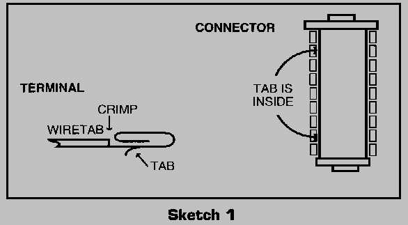
Sketch shows view looking into the connector from the terminal end, not the side where the wires enter.
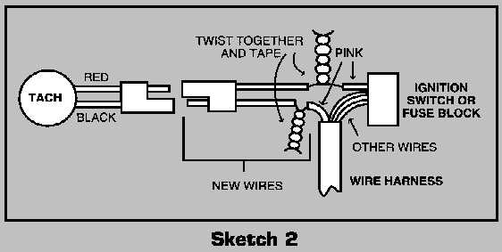
E. Find the coil circuit wire in the dash harness. This is the soft, fat, pink wire that comes through the firewall at the upper center. Cut the wire at the fuse block on 70's or at the ignition switch on 69's. Splice a wire pigtail in at this point to connect with the Tach wire. (See Sketch 2). Cut as close to the fuse block or ignition switch as possible. This type of connector pigtail can be found at most Radio Shack's, car stereo stores or auto part stores. (*Note - The ignition circuit runs through the tachometer. These circuits must be absolutely secure for your car to run reliably. Soldering and/or using a splice kit with heat shrink tubing is recommended.)
F. In the engine compartment, replace the large bell type oil pressure sender with the smaller pressure switch.
G. Remove the 3 wire harness [coil, temp, & oil] which runs near the driver side valve cover and measure the resistance of the oil pressure wire [center pin]. If it is original it should measure about 5 ohms. If it measures 0 ohms put it back on the car and go to the next step. If it measures 5 ohms, do one of the following two things: 1) replace with another harness that measures 0 ohms or 2) Untape the wires and splice in a new wire to bypass the length of resistance wire [black] and then retape. It should now measure 0 ohms. Reinstall it in the car.
H. Check the replacement Tach cluster flex circuit on the
back to make sure there are no breaks. Repair as necessary. This is also a good time to do
a general clean up of the whole cluster.
I. Install the Tach cluster in the dash.
J. Connect battery, start engine and test cluster.
K. Reinstall dash pad.
L. Install aftermarket voltage gauge per the manufacturer's instructions if desired.
And there you have it, your in-dash Tachometer!
* Note added in 2022 after original printing in newsletter and original web article.
This page last updated: November 6, 2023. All Rights Reserved.